
FINISHES
Positive Tactile Feel
Some designers are looking for a more positive tactile feel than traditional carbon pill keypads. Keyflex silicone keypads can achieve this by using a tact switch mounted on the PCB and the stem of the tact switch is seated behind the silicone key. One other method we use that doesn’t involve the extra costs associated with tact switches, their mounting costs or mechanical failure is the use of tactile snap metal dome switches on an adhesive layer which gives a broader design scope for key design as the force and feedback is not solely produced in the diaphragm of the keypad. The PCB cost is reduced and installation can be a simple peel-and-stick process (not necessarily required)
Laser Etched keypads
The laser etching process begins by taking a translucent coloured silicone material, which is then printed with the desired keytop design. This printed design serves as the base for the laser etching process.
The next step involves applying a thin layer of silicone paint over the printed keytop design. The paint acts as a protective layer for the underlying translucent ink and helps to provide a uniform surface for the laser to etch onto. After the paint has been applied, it is allowed to cure, which typically takes several hours.
Once the paint has cured, the laser etching process begins. A high-powered laser is directed onto the surface of the keypad, precisely etching away the silicone paint to reveal the underlying translucent ink. The laser is controlled by computer software, which allows for precise control of the etching process. This ensures that the etched characters are of the highest quality and that the etching is consistent across all parts of the keypad.
The laser etching process creates highly detailed, precise characters that are easy to read and legible. Furthermore, the process is highly repeatable, which means that multiple keypads can be produced with the same design, ensuring consistency between each one.
Finally, when the keypad is backlit, only the etched characters transmit light, making the keypad ideal for applications where excess light spillage would create problems for the user. This is because the laser etched characters allow light to pass through only in the areas where the silicone paint has been etched away, effectively blocking light in all other areas. This allows for highly customizable backlighting that can be tailored to the specific needs of the application.
Multi-coloured keypads
Multi-coloured keypads can allow many different key colours within the one keypad. We work to standard colour matching systems such as Pantone and RAL. In addition, we can match client supplied colour swatches in many cases. By applying the colour to the key, rather than printing the colour on the top of the key, the cost of the keypad is reduced and the risk of ink wear is minimised
Wear-resistant coated keypads
Wear-resistant coated keypads are achieved by applying a coating to the keypad after the post curing process. This means any printing or spraying are also protected by the coating. To avoid potential ink wear we recommend using a wear resistant coating in applications where the keypads will be subjected to high usage or will be used in a harsh environment.
Epoxy Coating Silicone Keypads
Epoxy coating can be left clear to display the printed ink on the keytop or can also be sprayed and laser etched. The epoxy coating can have either a gloss or a matt finish.
Plastic feel keypads/plastic keycaps
Plastic feel keypads/plastic keycaps in some applications our clients have chosen the cost savings and the ease of assembly offered by silicone keypads, but have requested a plastic keycap feel. This can be achieved by using plastic keycaps, or by applying an epoxy coating to the keytop. In addition, thermoformed keypads can be produced where the key height is low and the key travel short.
Thermoformed Keypads
Thermoformed keypads are produced using polycarbonate or polyester, which is printed on the rear surface and then thermoformed to fit over the keypad or plastic insert. The ability to create small, closely pitched keys makes them ideal for small hand held appliances where a keypad’s size is critical.
CONSTRUCTION AND DESIGN
INDIVIDUAL KEYS
Key design will vary with the functional and aesthetic requirements of the application. A designer may consider the options detailed in this section which show alternative key styles and the new possibilities for adding legends and backlighting to the design.
SNAP RATIO
The snap ratio of a keypad is directly linked to the tactile feel experienced by the user. Designers should attempt to maintain ratios of around 40-60% only dropping below this if they are prepared to compromise tactile to ensure longer life.
TACTILE FEEDBACK
The membrane shape and size of any rubber keymat can be designed to achieve almost any combination of actuation force and tactile response. Most applications simply require a positive tactile feel with a long life and as such an actuation force of 125-150grms, with an accompanying snap ratio of 40-60% is a good recommendation.
SWITCH LIFE
Membrane style and the durometer of the material are the factors that most effect switch life. Using a higher durometer silicone, increasing the actuation force or by increasing the stroke will all decrease life.
CONTACTS
Keyflex offer three different types of contact solutions, each with it‘s own unique characteristics. The carbon pill is most commonly used due to it’s long life (>10 million ops) and low resistance (<1000). The pills are usually circular with diameters ranging from 1.5-10mm and thickness from 0.4-0.6mm. Oval shaped pills are also Available..
PRINTED CIRCUIT BOARD DESIGN
Rubber keymats themselves are very reliable in operation but when considering PCB design, the environment that the keypads are to be used in must be taken into consideration to ensure the complete switching unit remains reliable.
MECHANICAL DRAWINGS
Our preferred method for quoting is by submitting a 3D drawing in STP or IGES format, however we can quote if you have a 2D dimensioned drawing or sketch. Alternatively, the Silicone Keypad Quotation details listed below can also be used to provide the information necessary for quoting a customer design
To assist our designers please ensure that the following information is included in the drawing:
Overall keypad size Base thickness
Keytop outside dimensions
Overall key heights
Contact size
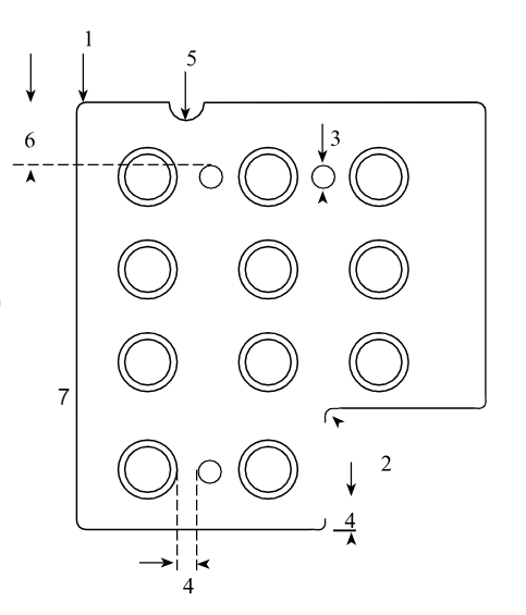
Mounting hole details
Mounting boss details
Dimensions (keypad and buttons
Keypad/switch colours
Stroke/travel
Actuation force Snap ratio Electrical specs Material specs Graphic colour(s)
Printing artwork
G E N E R A L
Operating Temperature: Storage Temperature: Operating Force:
Cycle Life:
Contact Resistance: Contact Rating: Contact Bounce: Insulation Resistance: Break Voltage:
Key Colour:
Key Size:
Key Shape:
Tactile Feedback:
Print Colour:
Conductive Rubber
Specific Gravity: Hardness Shore A: Tensile Strength kg/cm: Elongation %: Compression Set %:
Volume resistivity ohm-cm
1.06 – 1.18
60 – 65
65
Insulative Rubber
Specific Gravity: Hardness Shore A: Tensile Strength kg/cm: Elongation %: Compression Set %:
Volume resistivity ohm-cm Room Temperature
After 24 Hours @ 150• C
S P E C I F I C A T I O N S
-15• C to
-30• C to
50 to 350 grams
300,000 to 30 million
< 100 ohms 5mA@12VDC
< 12 milliseconds
> 1012ohms @ 500VDC
> 25-30KV/mm
Optional Optional Optional Optional Optional
300
15 – 25
4
1.10 – 1.40
35 – 80
50 – 80
400
18 – 20
2 x 10¹⁴
3 x 2014
Standard Conductive PIL sizes:
Diameter (mm) | 2.0 | 2.5 | 3.0 | 3.5 | 4.0 | 4.5 | 5.0 | 5.5 | 6.0 |
Thickness (mm) | 0.8 | 0.8 | 0.8 | 0.8 | 1.0 | 1.0 | 1.0 | 1.0 | 1.0 |
Please note that the Conductive PILs can be produced to almost any design, including PILs with the centre removed for backlighting using a LED mounted under the switch centre.
D I M E N S I O N A L
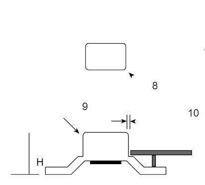
G U I D E L I N E S
- Minimum Radius 0.5mm
- Minimum Radius 0.25mm
- Minimum Diameter 1.5mm
- Minimum 2.0mm
- Minimum Radius 0.5mm
- Minimum 3.0mm
- Plastic Moulding
- If H< 7mm, minimum Radius 0.5mm
If H > 7mm< 10mm, minimum Radius 0.9mm
- Minimum 0.2mm
- Typical 0.15mm
Typical Tolerances (mm)
Typical Tolerances (mm)
Tolerance Normal | L < 10 + /-0.1 | L > 10, < 20 + /-0.15 | L > 20, < 30 + /-0.20 | L > 30, < 50 + /-0.25 | L > 50, < 100 + /-0.50 | L > 100 + /- 1.0% |
Critical | + /-0.05 | + /-0.08 | + /-0.10 | + /-0.15 | + /- 0.3% | + /- 0.5% |
Typical Application Specifications | ||||||
Appliance: | Key Travel (mm): | Actuation Force (gms): | Operating Life: | |||
Audio Equipment | 0.3–0. | 90–150 | 100,000 | |||
Car Radio | 0.3–0. | 150–250 | 300,000 | |||
Computer Keyboard | 2.5–3. | 50–90 | 10 million | |||
Remote Control | 0.3–1. | 90–150 | 500,000 | |||
Telephone | 2.0–4. | 150–250 | 1 million | |||
Video | 1.0–1. | 100–200 | ||||
TOOLING
All of Keyflex conductive rubber keypads and switches are compression-molded in precise carbon steel tools using highly elastic, non-toxic silicone rubber compounds. . Compression moulds have a bottom tool and a top tool (think of a waffle iron). Pressure, heat and time are used to transform the material to the shape of the cavity. Typical cycle time for silicone keypads is about 5-10 minutes – which is much longer than typical plastic moulding. After molding, all keypads are subjected to a two-hour post-curing cycle at a temperature of 200°C. Post curing is essential to the manufacturing process because it removes catalyst and oxidant residue retained by the keypad during the molding process, stabilizes the physical properties of the silicone and increases thermal stability.
CAVITITES
Tools can have single or multiple cavities. The more cavities the more expensive the mould will be but production cost per keypad will be reduced. For production runs of larger quantity a multiple cavity is recommended. Moulds of 100 cavities or more is possible depending on the design.
MODIFYING TOOLS
It is highly difficult to add inserts in compression keypad tools. It is far easier to simply remove steel from the tool. For this reasons the initial design of the part must be made with careful considerations to tool modifications. Existing moulds can have steel cut away (adding material to the part), but steel shouldn’t be added to the tool (remove material from the part).